Note
Go to the end to download the full example code.
Three Logical CNOTs#
This example demonstrates a computation involving three logical CNOT operations.
This example shows the construction and simulation results of three logical CNOT gates between three logical qubits with lattice surgery [Horsman et al.[1]].
Construction#
The three CNOT gates are applied in sequence.

tqec provides builtin functions in tqec.gallery.three_cnots to construct
three logical CNOT gates compressed in spacetime.
from multiprocessing import cpu_count
from pathlib import Path

import matplotlib.pyplot as plt
import numpy
import sinter

from tqec import Basis, NoiseModel, compile_block_graph
from tqec.gallery import three_cnots
from tqec.simulation.plotting.inset import plot_observable_as_inset
from tqec.simulation.simulation import start_simulation_using_sinter
graph = three_cnots()
graph.view_as_html()
The three logical CNOTs have six independent stabilizer flow generators:
XXX -> XII
XXI -> XIX
XII -> XXI
ZII -> ZII
IZI -> ZZI
IZZ -> IIZ
Here we show the correlation surfaces for the generators.
correlation_surfaces = graph.find_correlation_surfaces()
stab_to_surface = {s.external_stabilizer_on_graph(graph): s for s in correlation_surfaces}
XXX -> XII
graph.view_as_html(
    pop_faces_at_directions=("-Y",),
    show_correlation_surface=stab_to_surface["XXXXII"],
)
XXI -> XIX
graph.view_as_html(
    pop_faces_at_directions=("-Y",),
    show_correlation_surface=stab_to_surface["XXIXIX"],
)
XII -> XXI
graph.view_as_html(
    pop_faces_at_directions=("-Y",),
    show_correlation_surface=stab_to_surface["XIIXXI"],
)
ZII -> ZII
graph.view_as_html(
    pop_faces_at_directions=("+Z",),
    show_correlation_surface=stab_to_surface["ZIIZII"],
)
IZI -> ZZI
graph.view_as_html(
    pop_faces_at_directions=("-Y",),
    show_correlation_surface=stab_to_surface["IZIZZI"],
)
IZZ -> IIZ
graph.view_as_html(
    pop_faces_at_directions=("-Y",),
    show_correlation_surface=stab_to_surface["IZZIIZ"],
)
Example Circuit#
Here we show an example circuit of three logical CNOTs with \(d=3\) surface code
that is initialized and measured in the \(X\) basis. You can download the
circuit here or
view it in Crumble.
graph_x = three_cnots(Basis.X)
compiled_graph = compile_block_graph(graph_x)
circuit = compiled_graph.generate_stim_circuit(
    k=1, noise_model=NoiseModel.uniform_depolarizing(p=0.001)
)
Simulation#
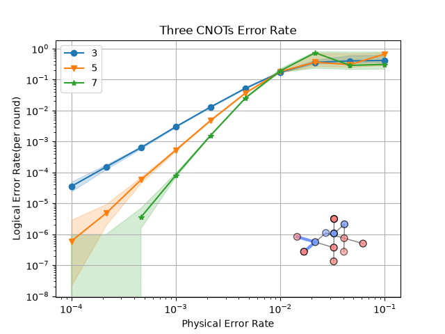
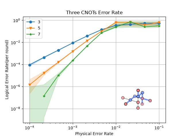
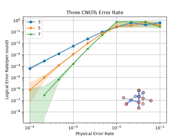
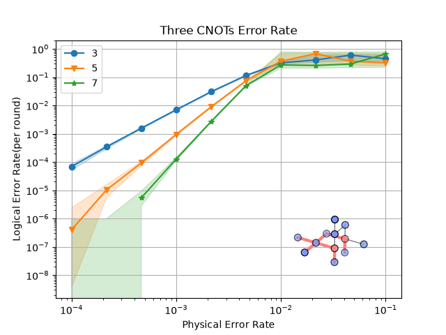
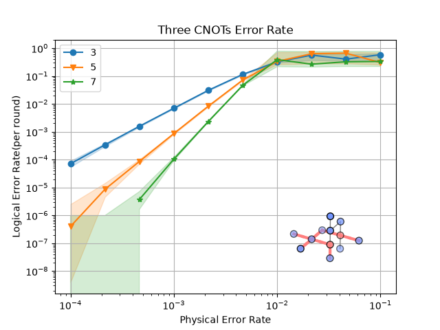
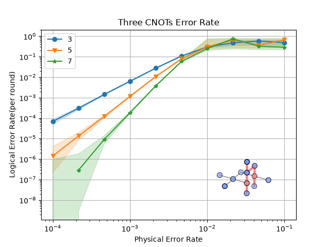
Here we show the simulation results for all six observables under a uniform depolarizing noise model.
def generate_graphs(support_observable_basis: Basis) -> None:
    """Generate the logical error-rate graphs corresponding to the provided basis."""
    block_graph = three_cnots(support_observable_basis)
    zx_graph = block_graph.to_zx_graph()

    surfaces = block_graph.find_correlation_surfaces()

    stats = start_simulation_using_sinter(
        block_graph,
        range(1, 4),
        list(numpy.logspace(-4, -1, 10)),
        NoiseModel.uniform_depolarizing,
        manhattan_radius=2,
        observables=surfaces,
        num_workers=cpu_count(),
        max_shots=1_000_000,
        max_errors=5_000,
        decoders=["pymatching"],
        save_resume_filepath=Path(
            f"../_examples_database/three_cnots_stats_{support_observable_basis.value}.csv"
        ),
        database_path=Path("../_examples_database/database.pkl"),
    )

    for i, stat in enumerate(stats):
        _, ax = plt.subplots()
        sinter.plot_error_rate(
            ax=ax,
            stats=stat,
            x_func=lambda stat: stat.json_metadata["p"],
            failure_units_per_shot_func=lambda stat: stat.json_metadata["d"],
            group_func=lambda stat: stat.json_metadata["d"],
        )
        plot_observable_as_inset(ax, zx_graph, surfaces[i])
        ax.grid(axis="both")
        ax.legend()
        ax.loglog()
        ax.set_title("Three CNOTs Error Rate")
        ax.set_xlabel("Physical Error Rate")
        ax.set_ylabel("Logical Error Rate(per round)")
Z Basis and X Basis Simulations
References#
Total running time of the script: (11 minutes 15.236 seconds)